I do a lot of repetitive things in the name of science…
…and if you’re here, I’m guessing you do too. One process I’ve probably done 10,000+ times is setting up a polymerase chain reaction (PCR). This winter, before my comparative genomics class, I was talking for my professor, Dr. Aaron Liston, about how many plates I needed to run just to get pre-liminary data for my MLO work (~50). He suggested I investigate robotics. Of course! How had this maker not considered that? So, after my amazing adviser (Dr. David Gent) gave me his blessing (to spend an inordinate amount of time on this what-I-thought-would-be-side-project) I scoured the internet and found numerous examples of scientists all over the world building their own liquid handlers (each with varying levels of documentation).
Opentrons
 Opentrons was probably the first fully open automatic liquid handler. They debuted back in 2015 with a kickstarter campaign. Their original OT-one design has X, Y1, Y2, Z, and A axes (A is for the pipette, which is driven by an non-captive nema stepper motor).
Ottobot
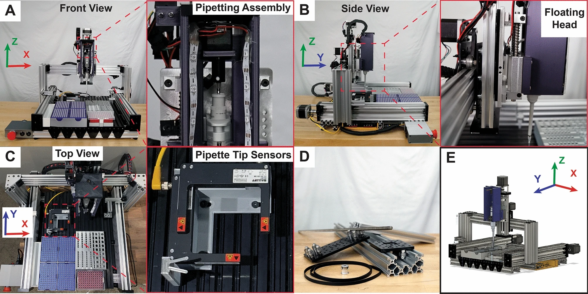 Ottobot was created in 2020 by Vanderbilt PhD student, David Florian. He roughly based his design off of the Opentrons OT-1 (X, Y1, Y2, Z, and A axes), but added additional limit switches and lasers to check for successful loading of pipette tips. He also included the very powerful (albeit not as easy to work with) TMC2660 stepper drivers which allowed him to harness the full power of the Nema 23 stepper motors. Opentrons had to reduce current in their firmware as their stepper drivers weren’t able to support the powerful motors.
Other liquid handlers
Pipette Jockey’s OT-One Pipette Jockey does an incredible job at rebuilding the OT-One. Check out his other builds too.
OpenLH This liquid handler uses a robot arm coupled with a syringe pump.
Open Workstation Full work station for cell culturing. They bought the Opentrons pipette though, which is why I didn’t follow their plans (I can’t drop $4k on a pipette).
EvoBot Evobot is like the OT-one but uses a syringe pump. It’s an impressive build.
Public Lab Pipetting Robot Impressive public build.
Idea
Alas, I was inspired by all of the available plans and by the “free and open-source hardware” (FOSH) movement. In theory, by building your own automated liquid handler, you can save money, customize your equipment, have more reproducible data, and expand access to scientific equipment globally (by reducing cost).
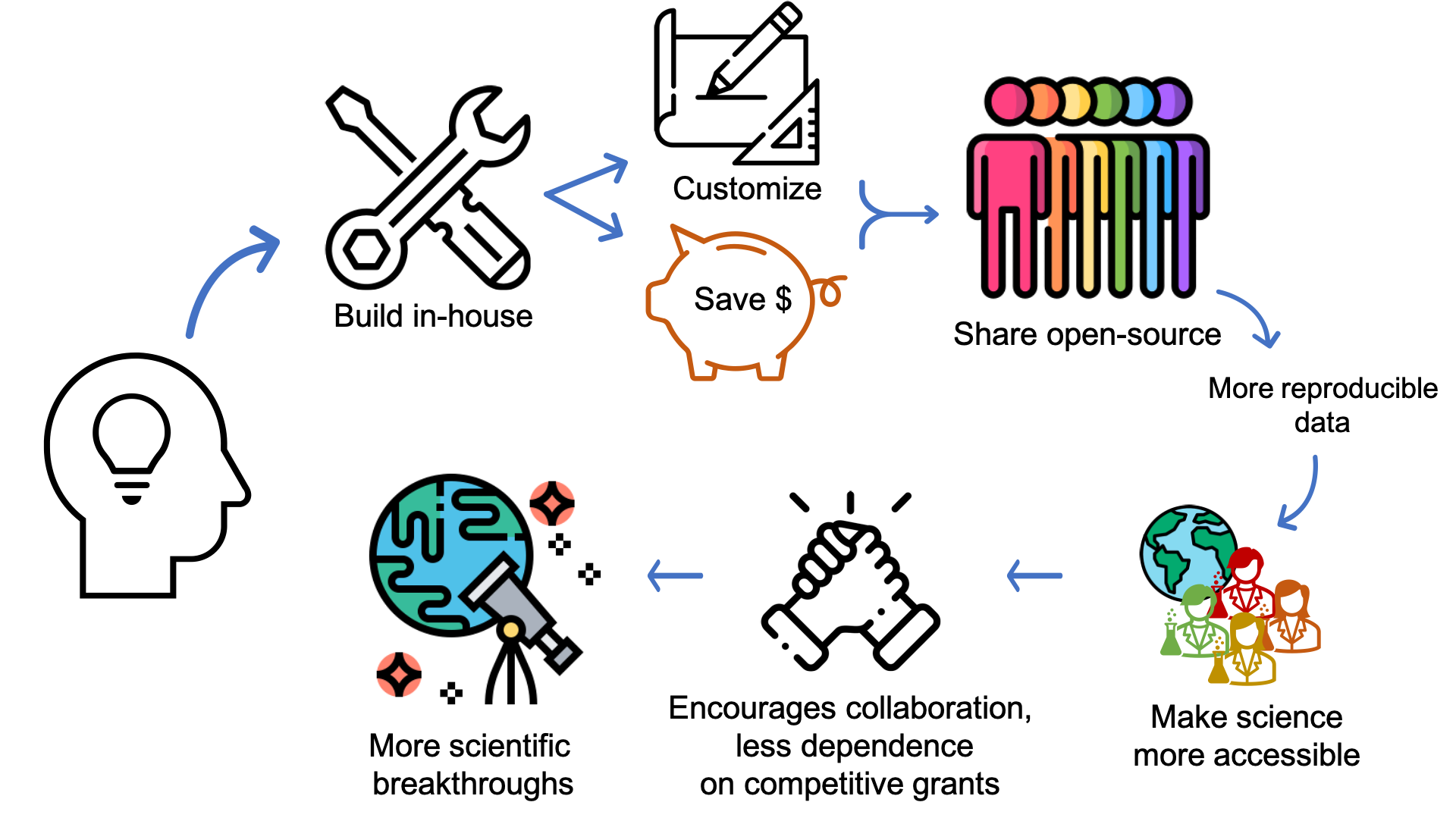
So, I tracked down one of my favorite YouTubers (who is also the inventor of Otto) and told him my plans. He was pumped and offered to help when he was able to. This is what I love about the maker movement: everyone wants you to succeed. This became quickly apparent to me after witnessing the effort that strangers made while trying to help me (message boards, neighbors, fab labs, library, Dr. D Flo, etc.).
Plan
First, I needed to acquire the necessary tools, and, quite frankly, learn a little more about electronics. I’ve been a maker my whole life, but mostly with wood. I’ve only dabbled in electronics with my van build, occassional repairs, and house projects. I’m definitely not proficient and often end up “jury-rigging” things.
Alas, I wanted to do things right this time around, so I picked up the necessary (and optional) tools, tried a few Arduino kit tutorials, and practiced my crimping. I also built up some misplaced confidence by assembling my own 3d printer (from a kit).
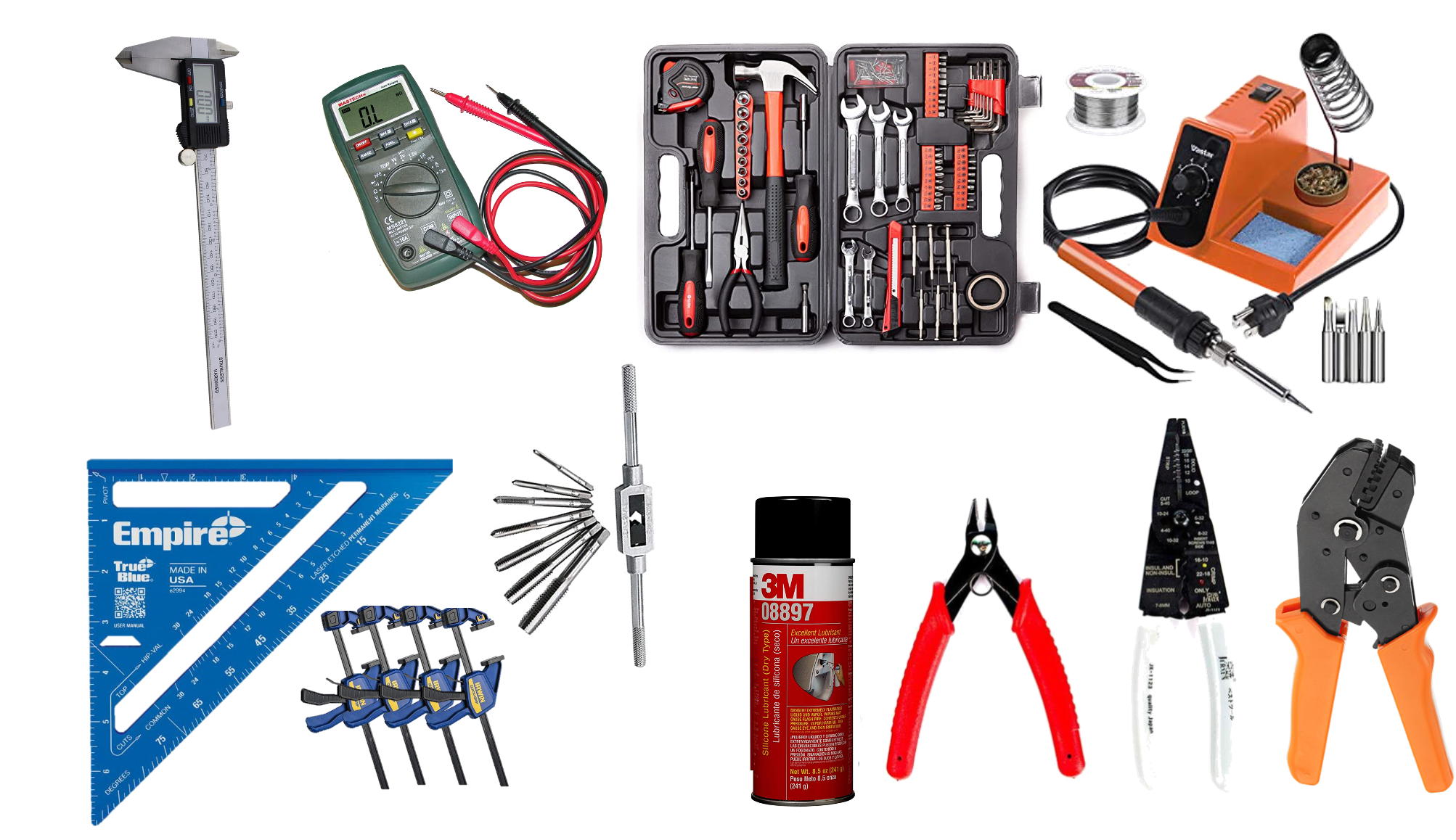
Necessary tools for this project:
- Metric allen wrenches
- Metric open wrenches
- Needle nose pliers
- Tape measure
- Precision calipers
- Crimpers
- Wire strippers
- M5 tap
- Multimeter
- Small screwdriver set
Potentially optional
- Soldering iron (can avoid soldering with connectors)
- Solder
- Solder remover
- Extra soldering iron tips
- Helping hands
- Clamps
- Corner squares
- 3D printer (check your local resources first)
Once I had built a few trivial electronics projects, I felt confident to take on the project. This is a classic case of “the less you know, the easier you think it will be.” It was also the middle of a global pandemic, so… I was longing for a project to help enable my research and get my mind off the death and despair of the world.
My plan was to follow David Florian’s Ottobot design as I thought he had made several innovative improvements over the OT-1 (and let’s face it, it’s also because he offered to help me over zoom). After getting his design to work, I was then planning on simplifying wiring, building a UV light enclosure, and then trying my hand at building a multichannel syringe-pump to use as the floating head (with eventual plans of making a complete PCR system with thermalcycler, centrifuge, and robotic arm).
Build
Note: This will be long and is not intended as something for you to build along with; it’s intended to be lessons for those interested in building a similar machine. Consequently, I’ve emphasized and tried to explain the mistakes I made. I’m hoping to put together a polished build video in the future.
So, I found cheaper alternatives to the components found in Otto’s Bill of Materials. In the end, this a was a mistake as some of the alternatives I ordered were not compatible (ex. the lead screw and couplers) and it ended up costing me a lot more time and money. I’ll post my final BOM once I have it fully calibrated.
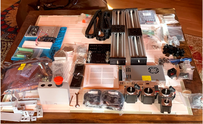
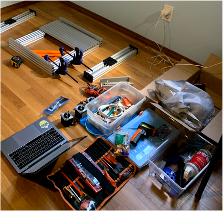
Here are most of the materials for the build. Not picture: aluminum extrusion for the bed and frame, pipette actuator, pipette, additional 3d printed components.
As pandemic “luck” would have it, I had a spare room open, so I moved the build into the spare room.
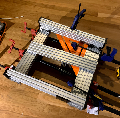
One of the essential parts to building a CNC machine is ensuring it’s square, so I used clamps and eventually two squares to make sure everything was squared nicely.
Slipping in the T-nuts so I can secure the bed. You can see the Ottobot Fusion 360 file open in the background. This is when I realized I needed to tap the aluminum extrusion… something I had never heard of. Tapping means threading a pre-drilled hole. The aluminum extrusion I ordered from Openbuilds had been predrilled, but not tapped. Alas, I went to harbor freight and bought a very terrible tapping kit. Do not buy it. Go buy a quality M5 tap - it’ll save you money, time, and blisters.
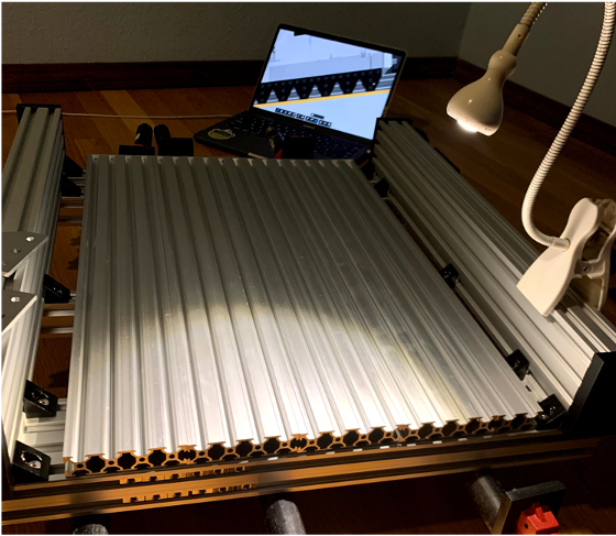
I found tapping to be difficult. I suggest practicing on something if possible. If you have a vice, then wrap your aluminum extrusion in a washcloth (to protect it) and tighten it down. This will make tapping so much easier. Once everything was tapped, I secured the T plates with 8mm M5 bolts and thus secured the liquid handler’s bed.
.gif)
This was one of the many mistakes I made during the build: trying to build the floating head while attached to the X-axis. If you take on this build, you should fully complete the floating head and then build the X-axis…that way you don’t have to undo/redo things a bunch of times. You can also see the comical mismatching or total absence of many bolts in this photo - this was not intentional. By not following David’s BOM exactly, I had miscalculated the number of bolts, and, apparently, M5 bolts are not available locally. Alas, I had to order more from Openbuilds. Since shipping was painfully slow during the pandemic, many of the upcoming pictures also have missing/mismatching bolts.
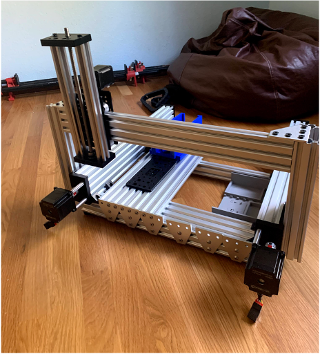
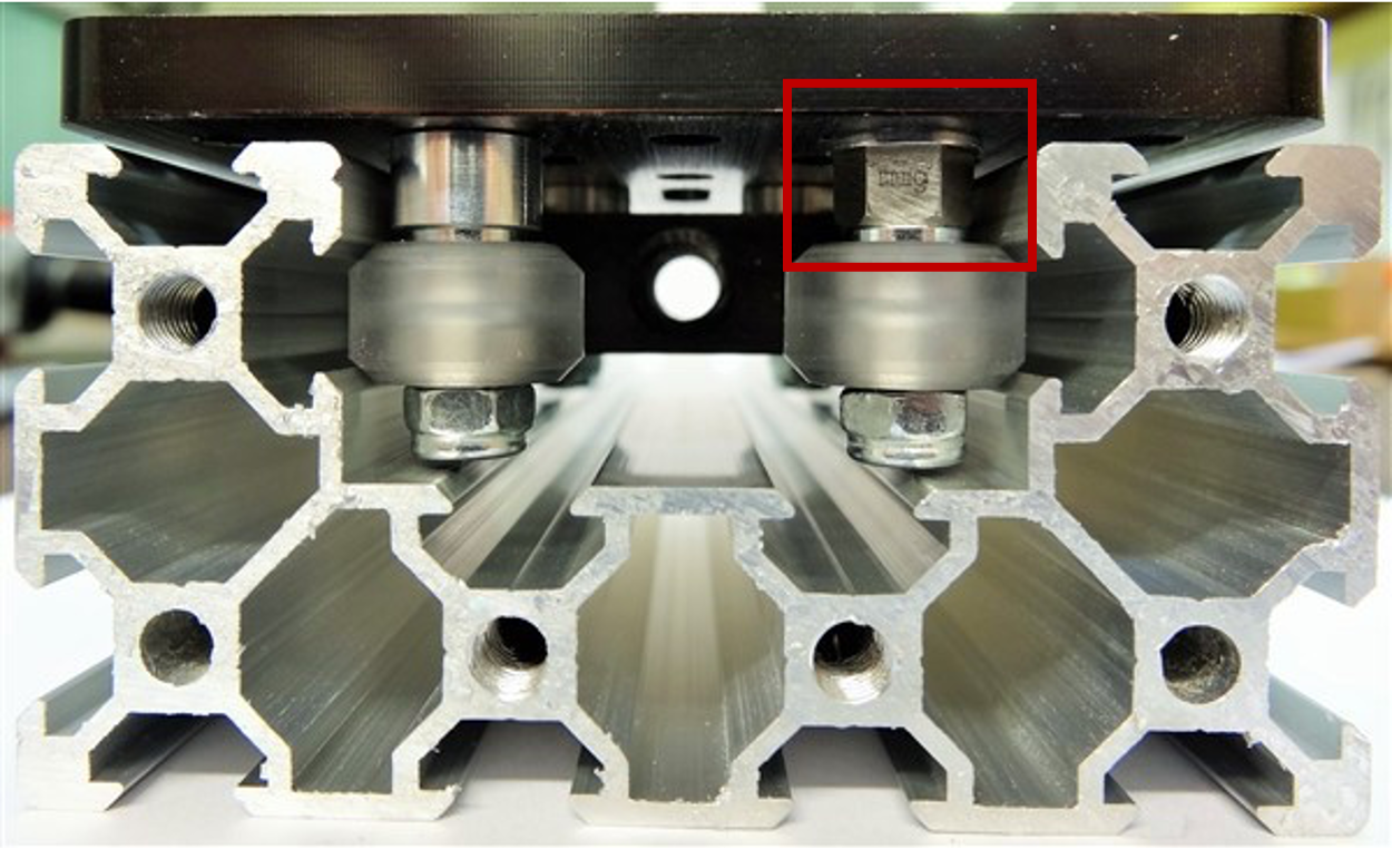
Still mismatching bolts 😆 , but I had assembled much of the floating head and X axis here. Eventually I’ll mill a gantry plate - I just need to find a mill locally. Gantry systems can be tricky due to the eccentric nuts/spacers. Eccentric nuts/spacers allow you to adjust the tension of your wheels to the aluminum extrusion (higher tension = greater accuracy, but also greater stress to the motor and wheels). A guide to adjusting eccentric nuts can be found here.
Now I needed to commit to buying the pipette actuator. This was night a light decision as this was the most expensive part of the build (~$200). I looked on eBay for months… but no non-captive stepper motors that would produce the same force and microstepping we needed. Alas, I ordered it and then had to step away until it arrived.
Pardon the mess… it’s a reality when you have a thousand small pieces and no real workspace. 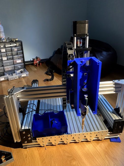
In the meantime, I thought I’d try to get the motors moving, as per Dr. D Flo’s (David Florian) suggestion. This is when I really started realizing how little I knew. I bought the TMC2660 breakout board stepper drivers (as per Ottobot BOM) and I didn’t know the first thing about breakout boards or stepper driver… I literally had to google all of those words. I tried putting jumper cables through the holes in the breakout board on a breadboard but wasn’t able to get a good connection. Alas, I realized I need to solder “headers” onto these boards. I also realized that these boards were too wide for a breadboard, so I literally hacked a breadboard to make them work (see here.
I’m still not great at soldering, but I’ve learned flux makes it so much easier. Be sure to tin your soldering iron and fully heat your contact before applying solder. Here’s a great soldering guide. 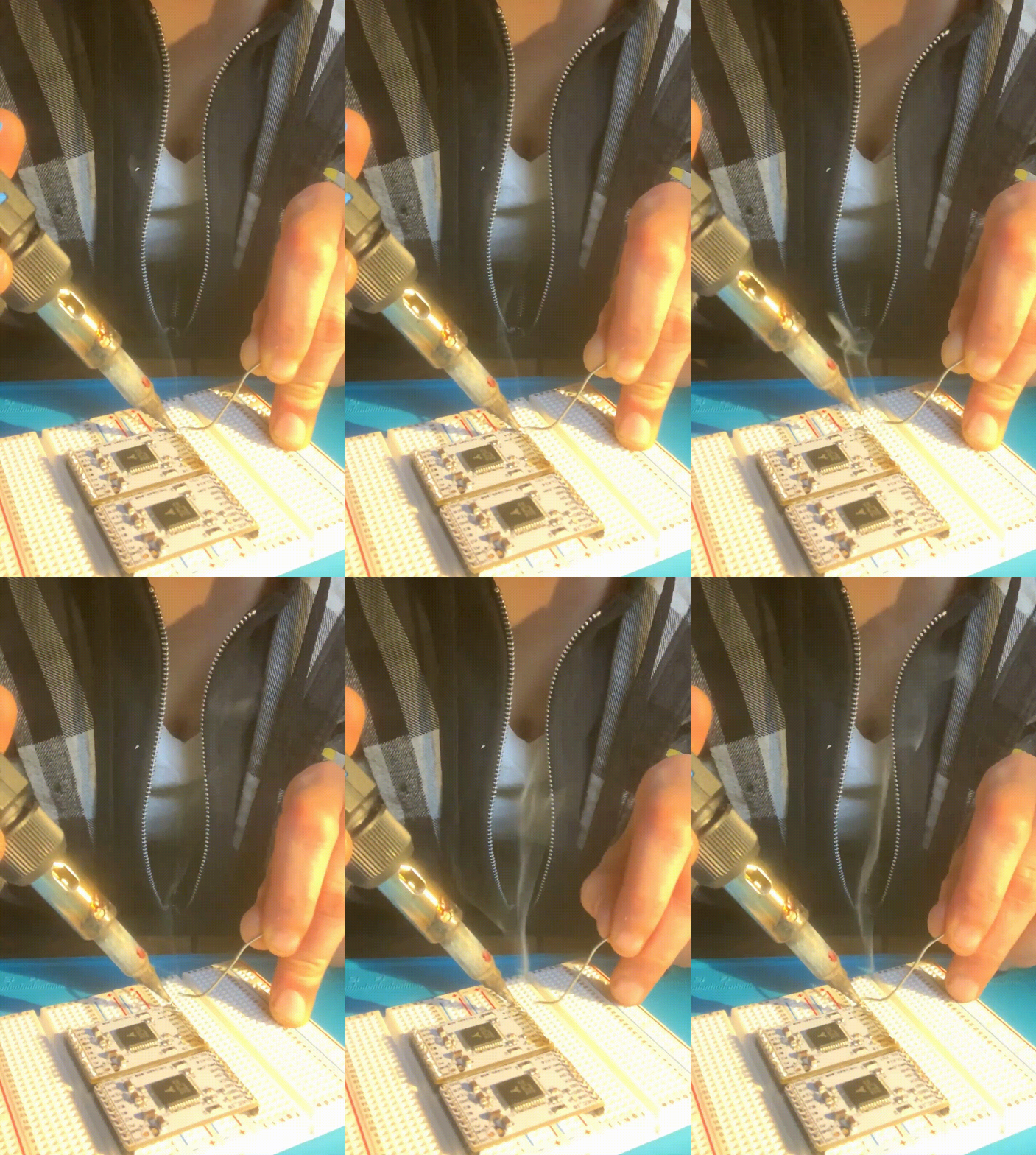
Alas, I spent many, many hours (and at least two Arduino Dues) trying to get David’s incredibly complex wiring to work. I have so much respect for his wiring skills, but after ~20 or so hours troubleshooting, I was pretty disheartened. I had A4988 stepper drivers on hand and I could get them to move my Nema 11 stepper motor, but I couldn’t get anything to move with the TMC2660 breakout board stepper drivers. I still don’t have an answer to this. Feel free to shoot me feedback.
Here’s my first major failure. I directly wired my 24V power supply to my Arduino Due. Poof! RIP. Newbie mistake. Most microcontrollers can’t handle more the ~3V. 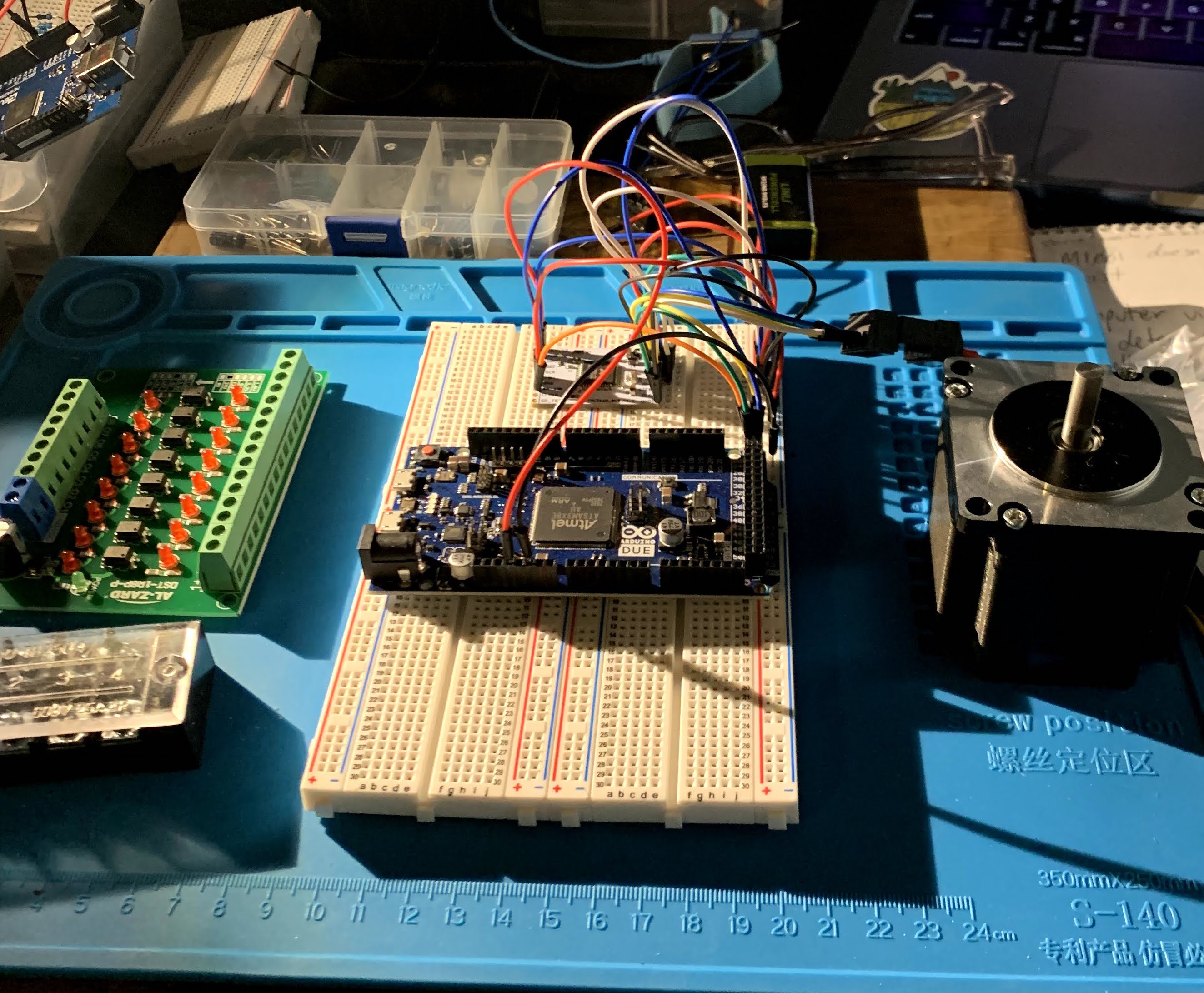
Alas, I made sure to not to wire high voltage directly through my next Arduino Due. 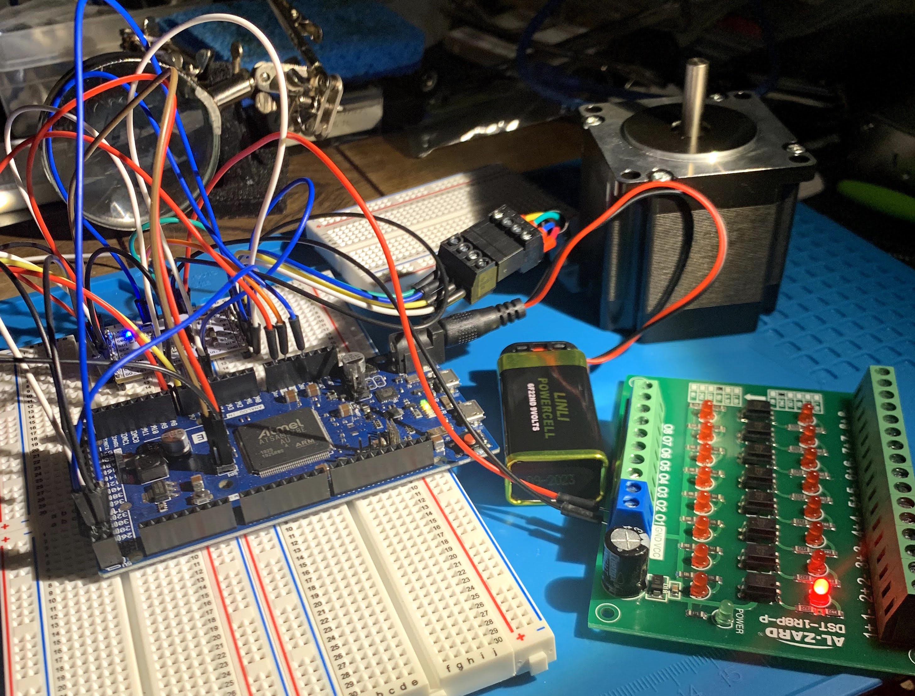
But, no matter what I did, I couldn’t get any of the example Arduino files to run the motors. I tried uploading different firmware, I tried the Arduino IDE, I tried pronterface, etc. I checked the power draw to the motors (with a multimeter) and it found it to be around 1.2V. This didn’t make sense as these motors needed more power than 1.2V. Alas, it had to have been something in my wiring (perhaps an improper ground?). I wired and re-wired and tried not to lose my mind. I decided that I needed to step away for a bit to regroup and then try to tackle the project with simpler wiring and software.
So, with David’s help, I explored options to simplify the wiring and software. I was interested in finding a chip with integrated stepper drivers as this would remove ~30 wires; unfortunately, not many chips have integrated stepper drivers that can run the very powerful Nema 23 stepper motors I had ordered for the project (they’re max power intake is 3A). I was also interested in finding a chip that could run the Opentrons software (which runs on Smoothieware firmware). David’s software is great, but at the time, it only worked on Windows and I didn’t own a windows computer.
That left me with very few options, especially for someone who doesn’t know enough to circumvent the pitfalls of each option.
- Smoothieboard v 1.1 This wouldn’t be able to provide full power to the Nema 23s, but could work.
- Smoothieboard v 2.0 This would be the perfect solution, but had not yet been released. I did try playing with PCB design for a minute though to see if I could get it working… then I realized I was definitely not an electrical engineer.
- Duet2 This doesn’t run on Smoothieware, though had the right stepper drivers.
- SKR 1.4 This would work, but had poor documentation.
Alas, I ordered the SKR board and a Smoothieboard v 1.1. The Smoothieboard took eons to arrive, so I gave an A effort to get the liquid handler running with the SKR board and TMC5160 stepper drivers. Ultimately, I was overwhelmed by the amount of necessary firmware changes and the contradictory documentation of necessary physical modifications to use the TMC5160 stepper drivers. This would probably be a great setup for someone with more experience (shoot me a memo if you’d like to give it a shot… I have the chips). In the meantime: I tried to go for low hanging fruit to maintain my morale. I replaced all the mismatching screws, designed a fun new faceplate, printed cable management clips, and started designing an enclosure. Aesthetics.
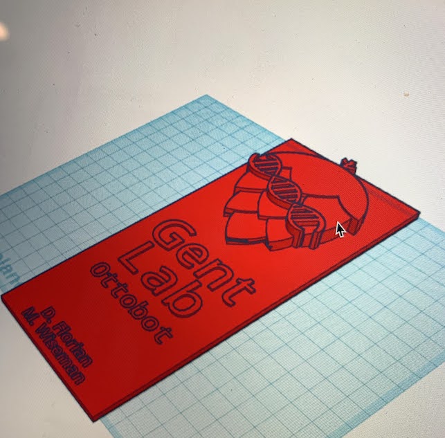
Once the Smoothieboard arrived, I flashed the OT-one firmware and config file to it.. I then went through the arduous process of changing all the motor connections. AGAIN. Why can’t these boards just share a common connector? Fortunately, the Smoothieboard ships with the necessary connectors, so it’s just a matter of cutting the old wires, stripping, crimping, and inserting in the provided connector.
To get an idea of Smoothieboard setup, you can see this diagram from Arthur Wolf (co-creator). It’s the original in the picture, but you get the idea: lots of setup is required. 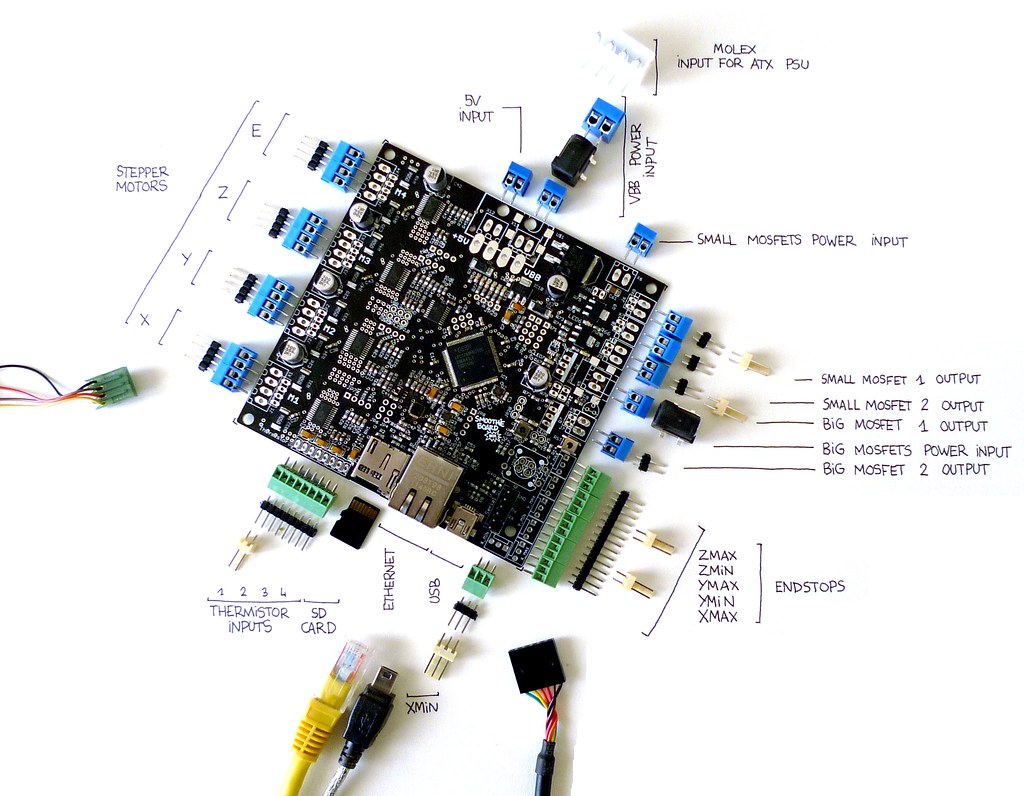
Fortunately, Smoothieboard has very thorough documentation and a large community that offer help. This was the magic answer. I needed to choose a board that had good documentation and lots of help. I needed to ask for and accept more help. Once I did this, everything started working flawlessly-ish. This is probably a lesson I should have learned from my previous yearly evaluation from Dave (my adviser), ‘Michele, you’re doing great, but your life would be easier if you asked for help earlier and more frequently.’ 🤦♂️ Perhaps I’m too stubborn for my own good.
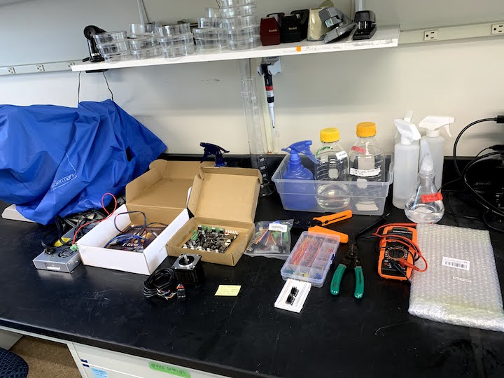
Alas, once I had finally achieved movement from the motors, I went about wiring up my Ottobot-remixed liquid handler. I used 3d printed cable clips (and here), drag chains, and zip ties for cable management. Eventually I might put some sleeves over the cables too, but for now it’s okay. There’s some great tips on wiring here.
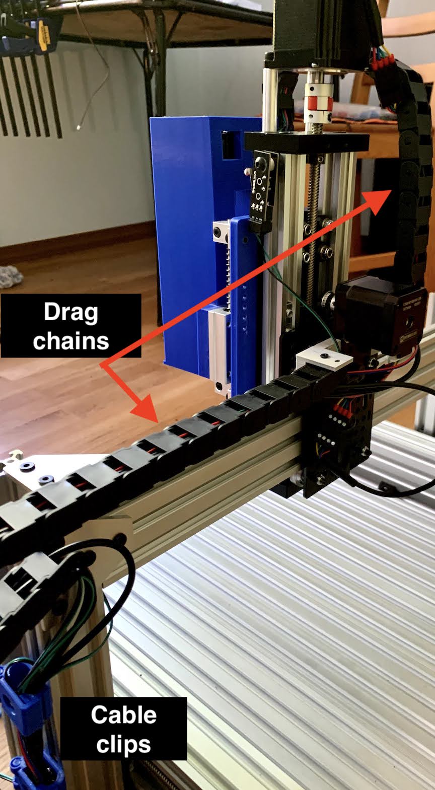
I decided to also wire up a computer fan as the stepper drivers were quite hot in the demo run (not pictured). Eventually I’ll probably swap the on-board drivers out for high power stepper drivers, but they seem to work okay for now. We’ll see how the compare to the actual Opentrons robot once I get the pipette installed (I’m building a sturdier pipette holder). Overall, the wiring is just so much simpler. I did have to jumper the two Y-axes together (following the OT-one firmware to tell me where), but that was pretty simple (see below).

So, here I am. The Ottobot-remix runs well with pronterface and I’m working the kinks out with the Opentrons software.
Next steps:
- Print and install studier pipette holder
- Machine gantry plate to add stability
- Add external stepper drivers (more power)
- Benchmark against OpenTrons Liquid Handler
- Build multichannel syringe pump
- Build UV enclosure
June 21st, 2021
After a much needed step away from the liquid handler project - I am back! Unfortunately, some issues arose with my 3d printer, so I had to repair that before I could continue with Otto. Alas, everything is now fixed and it’s time to optimize!
While I was able to get Otto moving with pronterface and small changes to the OT-1 firmware, things weren’t moving as fast as I’d expect them to (and they were heating up). This is likely partially due to the current limitations of the on-board stepper drivers. The Y and Z motors used for this CNC have a max rating of 3.0A and the on-board drivers can only deliver a max of 2.0A. While 2A is plenty for the pipette and X axis motors, I need to beef things up for the Y and Z motors. Also, it’s important to mention that running stepper drivers at maximum capacity is a bit of a safety risk as they will start to run hot.
So, I ordered some beefy DM542T stepper drivers which are capable of delivering current up to 4.2A and can also be programmed to 1/128 microsteps which should be plenty for 384-well plates. The only real drawback is that they are quite large, so it looks like I’ll be building a larger electrical case.
Power calculations
Do I have enough power for these badboys? Let’s do some math.
P = power
n = number of stepper motors
I = motor rated current
V = driving voltage (V = I x R)
1.2 = meaning 20% of margin (some power loss to heat)
For the Nema 23’s
n = 3 (Y1, Y2, and Z axes)
R = 1.1ohm (From datasheet)
I = 2.8A (From datasheet)
V = 3.08v (Calculated)
For the Nema 17
n = 1 (X axis)
R = 1.65ohm (From datasheet)
I = 1.68A (From datasheet)
V = 2.78v (Calculated)
For the Nema 11
n = 1 (P axis)
R = 2.1ohm (From datasheet)
I = 1.0A (From datasheet)
V = 2.1v (Calculated)
P = n x I x V x 1.2
P = (3 x 2.8A x 3.08v x 1.2) + (1 x 1.68A x 2.78v x 1.2) + (1 x 1.0A x 2.1v x 1.2) =39.12
So, if I wanted to run these at full power, I would probably opt for a bigger power supply (48V). Because the application necessitates precision (and not necessarily torque), I won’t be running these at full power. Instead, it’s more likely I’ll be running the X and Y and Z axes at ~1A and the P axis at ~500mA which puts me well within the limits of my 24V power supply. More power = more heat and more noise.
Wiring the DM542 drivers
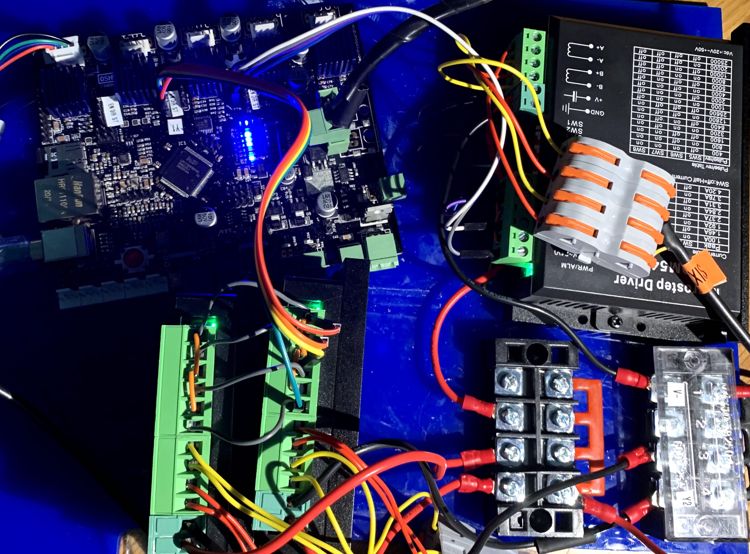
Wiring for these is a little tricky, but nothing like wiring mess of the external TMC2660BOBs. Plus, I tried to make it as easy as possible with a super detailed diagram.
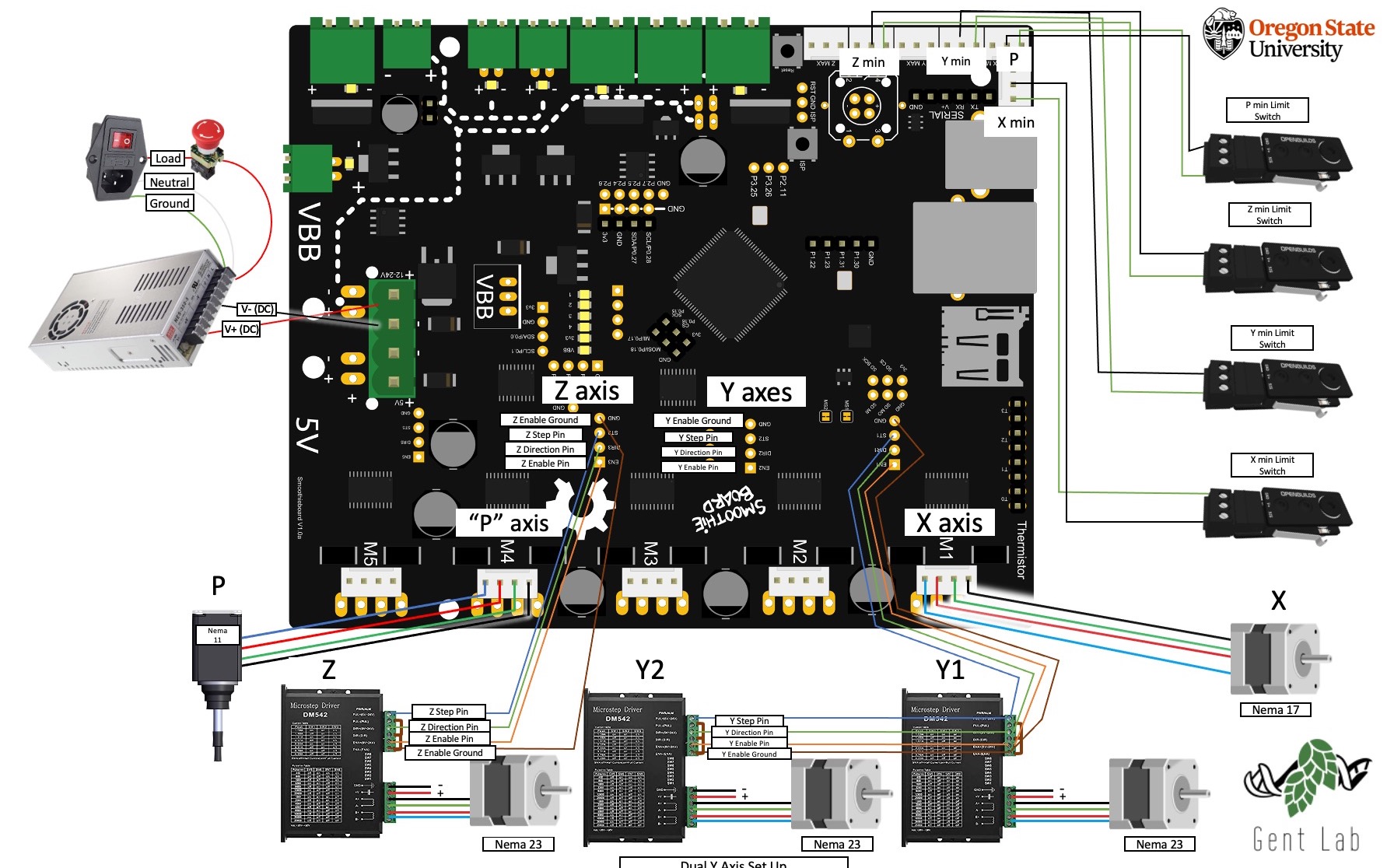
A few things for clarity:
- The +/- leaving the DM542s are directly connected to a either a + or - (terminal block)[https://www.amazon.com/URBEST5-Position-Covered-Screw-Terminal/dp/B01CG2HI0E/]. This terminal block is then directly connected to either the V+ or V- on the power supply.
- The switches on DM542s can be set a variety of ways; I currently have mine set to microstep at 1/32 (off, off, on, on) and deliver ~1 - 1.65A (I’m still fine tuning this).
- I used the common cathode configuration, but there are other configuration methods if your setup is different.
- The pipette tip detection switches aren’t pictured, but, essentially those can go pretty much anywhere that there is an open signal pin (see pin out.
And for some very rough photos…
First let’s start with the original wiring schematic; granted, this is simplified because it doesn’t include the limit switches, but you get the idea. It’s intense. 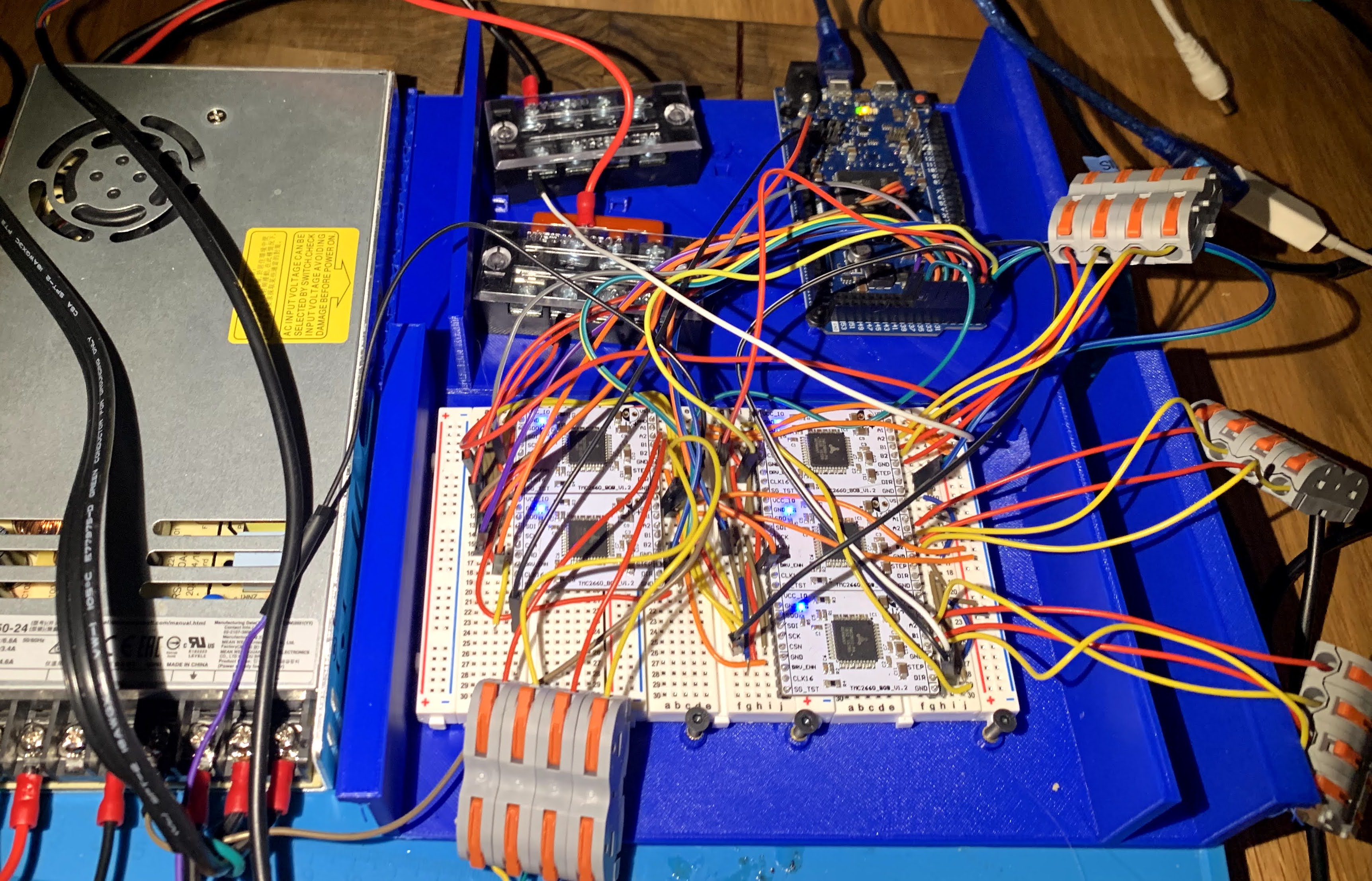
Now, the simplest wiring by far was just the smoothieboard and limit switches; however, the integrated stepper drivers just aren’t powerful enough to run the 2.8A Nema 23s, so I kept it as simple as possible by only including the necessary external stepper drivers. Two switches are missing, but that’d just be three more wires. All-in-all, much simpler.
Electronics enclosure
I decided to make a clear electronics box enclosure, so everything would be kept safe and because I like visually inspecting the wiring without unassembling everything. It’s pretty maddening when wires come loose every time you move the machine, so enclosures are a good idea. The basic principle for building my electronic enclosure can be found here.I used a CNC router cut out the acrylic case and mark the joints. I then routed some venting and dados so I could slide on the top. Finally, everything (except the sliding top) was glued with CA glue. pictures coming soon
Making the remix Opentrons compatbile
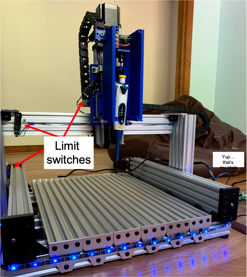
Unfortunately I then discovered that my limit switches were wired in conflict with the Opentrons software, so I repositioned all of my limit switches to reflect the X/Y/Z min (with the pipette sensor seated at Xmax). Next, I compiled the custom Linux OS for Opentrons and uploaded to a Raspberry PI 3+. I then connected the Raspberry Pi to the Smoothieboard with a crossover ethernet cable. I specified a static IP in my Smoothieware firmware and then directed the Opentrons software to that static IP.
Voila!! I now have a Opentrons compatible liquid handler.
To be continued…
Eventually…? These are pipe dreams.
- Robotic arm
- Robotic centrifuge
- Open real time thermal cycler
.JPG)